Lesson 2: Connecting LED. Making Traffic light
In this lesson we will work with LED, learn how to connect wires to Arduino, and Upload a code.
Hardware parts for this lesson:
- Arduino board
- Breadboard
- LED
- 220 Ohm resistor
- 2 pieces of jumpers (wires)
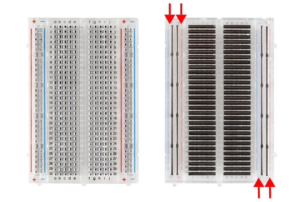
Breadboard comes as grid of slots. In a picture below you may see parallel lines with numbers 1,2,3,.... In each line there is 5 slots. Be careful, grid with "a,b,c,d,e" slots are different with "f,g,h,i,j" slots. On sides +/- grid, which comes through the length of breadboard.
Schematic diagram:

Scheme on breadboard:

Note: every LED has Anode - Cathode sides. Anode (plus) side, always is longer than Cathode (minus) side. Resistors do not have plus or minus sides, you may connect it with any side.
Code:
void setup()
{
// initialize 13 pin as output
pinMode(13, OUTPUT);
}
void loop()
{
//give HIGH signal to 13th pin, which means turn on
digitalWrite(13, HIGH);
// pause on 1 second
delay(100);
//give LOW signal to 13th pin, which means turn off
digitalWrite(13, LOW);
// pause on 1 second
delay(1000);
}
When everything is finished, just upload your code and watch the result.
Self-task: Take 2 more LEDs and make "Traffic light". Do not forget to take 2 more resistors for LEDs.


